Today, I am going to lead you through a tutorial of how to build a graphical (slightly UML-like) editor for the structure of an MPS language. The main goal of this tutorial is to show you how to use the diagram editor and querylist plugins that have been developed by Itemis as part of the mbeddr platform, without which building such a graphical structure editor would be at the least very much effort. It is assumed that the reader knows at least MPS basics (languages, structure, editors, etc.).
The code for this tutorial can be found at https://github.com/DSLFoundry/mps-graphicalstructureeditor and the MPS used contains at least the mbeddr.platform plugins (which contain querylist and diagram editor). An earlier post deals with the installation of these plugins into MPS.
As a side note: Itemis and JetBrains (and more contributors, such as DSLFoundry) are currently collecting and maintaining very useful plugins, such as the diagram editor in the MPS Extensions (more documentation here).
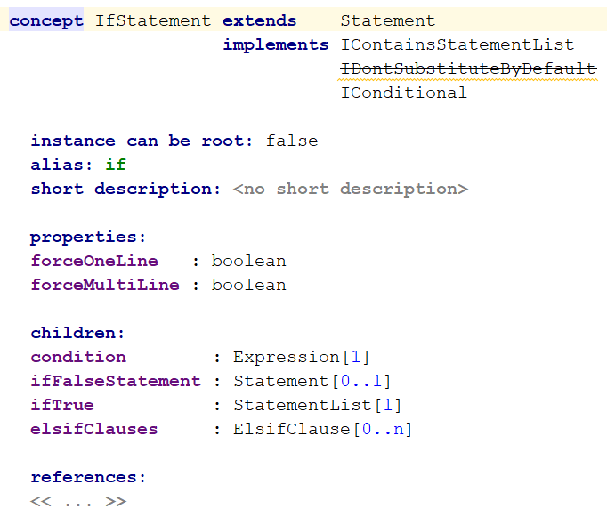
So, before we start with the nitty gritty details, let me explain to you what I mean by a graphical structure editor: let’s recall that the MPS structure aspect is at the core of language definition. With the current structure definition, each concept has a structure definition. An example of the java if-statement concept structure definition from MPS baseLanguage can be seen here:
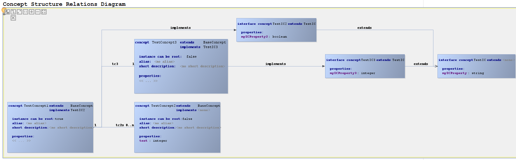
Let’s create a simple language (let’s say we call it com.dslfoundry.testlanguage, or testlanguage for short) that we will experiment with while building our graphical structure editor. The following diagram shows the structure of testlanguage:
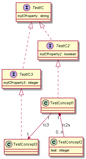
We have various concepts (TestConcept1, TestConcept2, and TestConcept3), interface concepts (TestIC, TestIC2, TestIC3) as well as relationships, such as implementation (e.g. TestConcept1 implements TestIC2 and TestConcept3 implements TestIC3), extension (e.g. TestIC2 and TestIC3 extend TestIC), containment (e.g. TestConcept1 has a list of children called tc2s which are of conceptTestConcept3), and reference (e.g. TestConcept1 has a reference called tc3 which is of concept TestConcept2).
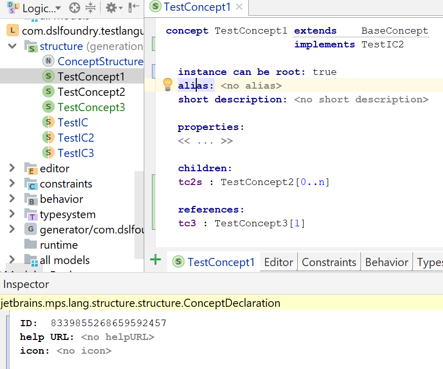
Normally, one would have to define the structure of TestLanguage by filling in the structure aspect for each concept. For example, for TestConcept1, the structure would be:

But we are not going to use the “normal” way to define the structure. Instead, we will make a new language called com.dslfoundry.graphicalstructureeditor (or graphicalstructureeditor for short), with which we will be able to (with some limitations) edit the structure of testlanguage.
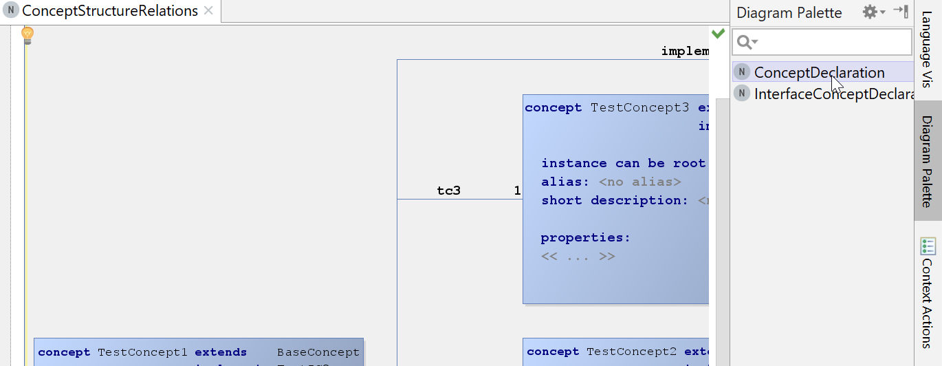
Let’s first make some decisions on how we want the graphical structure editor to look like and how we want it to be used. For the looks, let’s go for a box-line “roughly UML-like” look, i.e. concepts and concept interfaces are represented as boxes and relations between concepts are represented as labeled lines. Now, for the usage: since we want to edit the actual structure of a language, it makes sense to extend the language in MPS that is used to define the structure aspect. This will give us a simple entrypoint for our new language, enabling us to just right-click on a language’s structure and add an editable diagram to the structure Let’s first find out which language we want to extend: if we go to a concept (e.g. TestConcept1 of testlanguage) and then visit the inspector, we can see that a concept’s declaration is an instance of jetbrains.mps.lang.structure.structure.ConceptDeclaration:
So the language we want to extend with the graphicalstructureeditor language is jetbrains.mps.lang.structure. We can just add this as an extends dependency to the graphicalstructureeditor dependencies tab under language properties (select graphicalstructureeditor language and Alt+Enter, or right click –> properties).
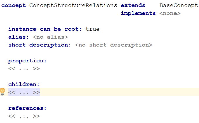
We’re going to choose to have one concept representing the language structure diagram. Let’s call it ConceptStructureRelations (right-click the structure of the graphicalstructureeditor language and choose new concept):
Now, since the diagram editor needs to render concepts, we will start defining relations, which leads to the rest of the graphicalstructureeditor language design:
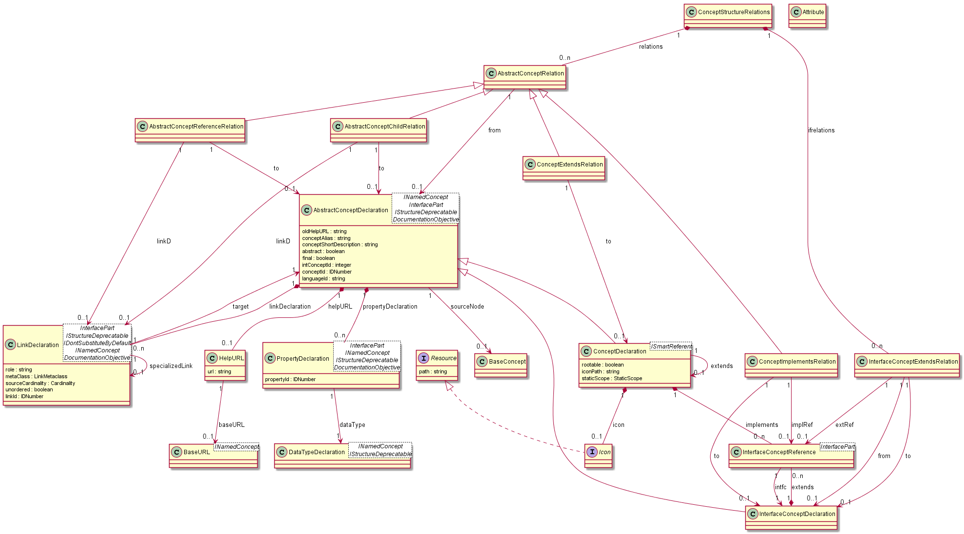
Just to highlight what the above language design is about: the ConceptStructureRelations diagram contains relations (of concept AbstractConceptRelation) and interface relations (of concept InterfaceConceptExtendsRelation). There are a number of concrete relationships extended by AbstractConceptRelation, namely: AbstractConceptChildRelation, AbstractConceptReferenceRelation, ConceptExtendsRelation, and ConceptImplementsRelation. The finished structure declaration is left as an exercise for the reader or can be found in the example code.
Now that we have defined the structure of our graphicalstructureeditor language, we have the context to start using diagram editor, which is one of the topics of this tutorial. But before we can do that, we need to set up a little bit more context: since we want to represent a ConceptDeclaration in an alternative notation (namely as a box in a diagram) without interfering with the existing “normal” textual notation of ConceptDeclaration, we have to add some editor hints to our language, so that we will be able to switch between the graphical and the textual notation. We do this by adding a hints definition called graphicalStructureHints (right-click the editor aspect of the graphicalstructureeditor language and choose New –> ConceptEditorContextHints):
![]()
Now, let’s start by making the editor for ConceptStructureRelations, which is supposed to be a diagram editor. When making an editor for a concept (e.g. double click the concept in the logical view, go to the editor aspect tab and choose new concept editor), the initial editor definition (after clicking on the <default> text in front of the “editor for concept” text and choosing the graphical hint: Ctrl/Cmd+Space –> graphical) looks like this:
![]()
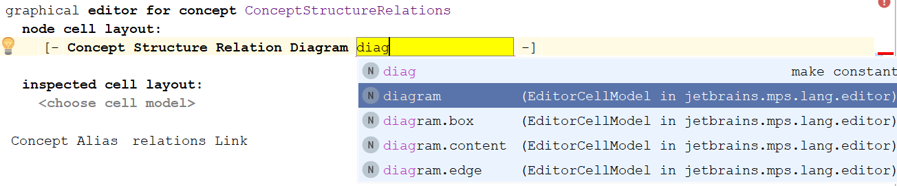
We can start the normal way by adding the title for the diagram, e.g. by typing “Concept Structure Relation Diagram” which will turn the text into a constant in the editor and then surrounding it by an indent collection (Alt+Enter –> Surround with Indent Collection). Now we add another cell (press Enter) and this is where we want to insert a diagram. To do this, we first import the diagram editor language (Ctrl+L+L, search for de.itemis.mps.editor.diagram and select it for import). Now we can choose diagram, which will insert a diagram cell:
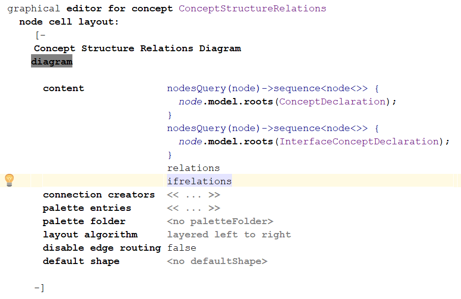
Let’s put the diagram on the next line (go to the constant text cell before the diagram, press Alt+Enter –> Add new line) and we get:

Let’s start with specifying what the contents of the diagram will be. We will want to show all concepts (ConceptDeclaration from jetbrains.mps.lang.structure), all interfaces (InterfaceConceptDeclaration from jetbrains.mps.lang.structure) as well as all relations (which are the lists of relations and ifrelations) in the graphicalstructureeditor language. The latter two can simply be completed from the rolenames of the ConceptStructureRelations concept (for which we are currently defining an editor). Since we don’t have the full set of concepts and interface concepts accessible from this concept, we need to somehow query them together. The diagram editor language provides a nodesQuery construction for that where we can just plugin an smodel query. But what smodel query to write? Let’s start with a nodesQuery for all ConceptDeclarations: imagine that we have a ConceptStructureRelations diagram as part of a language’s structure. Then we would want all the ConceptDeclarations of the language’s structure. Now we need a little bit of MPS architecture knowledge: MPS doesn’t really make a difference between languages and solutions; both are actually modules which contain models. So a language is just a module and each of its aspects is a model. That means that the structure of a language is a model. This knowledge enables us to write an smodel query, which will simply be node.model.roots(ConceptDeclaration), meaning “all the nodes that are instances of ConceptDeclaration in the model where node (in this case the diagram) resides”. The InterfaceConceptDeclarations are queried in an analogous way, leading to the following total specification for the diagram contents:
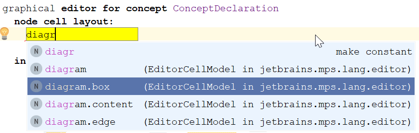
Before we go further with the diagram editor, let’s first add a box editor to the ConceptDeclaration concept. Since we are going to add an editor in our language for a concept that is not in our language, but in jetbrains.mps.lang.structure, we just right-click the editor aspect of the graphicalstructureeditor language and choose New –> Concept Editor. Then we choose again the graphical hint (see earlier) and ConceptDeclaration after the text “editor for concept”. Now, similar as for the ConceptStructureRelations, we add a cell from the diagram editor, but instead of the diagram cell, we choose the diagram.box cell:
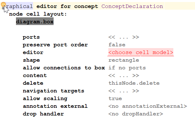
The resulting editor will look as follows:
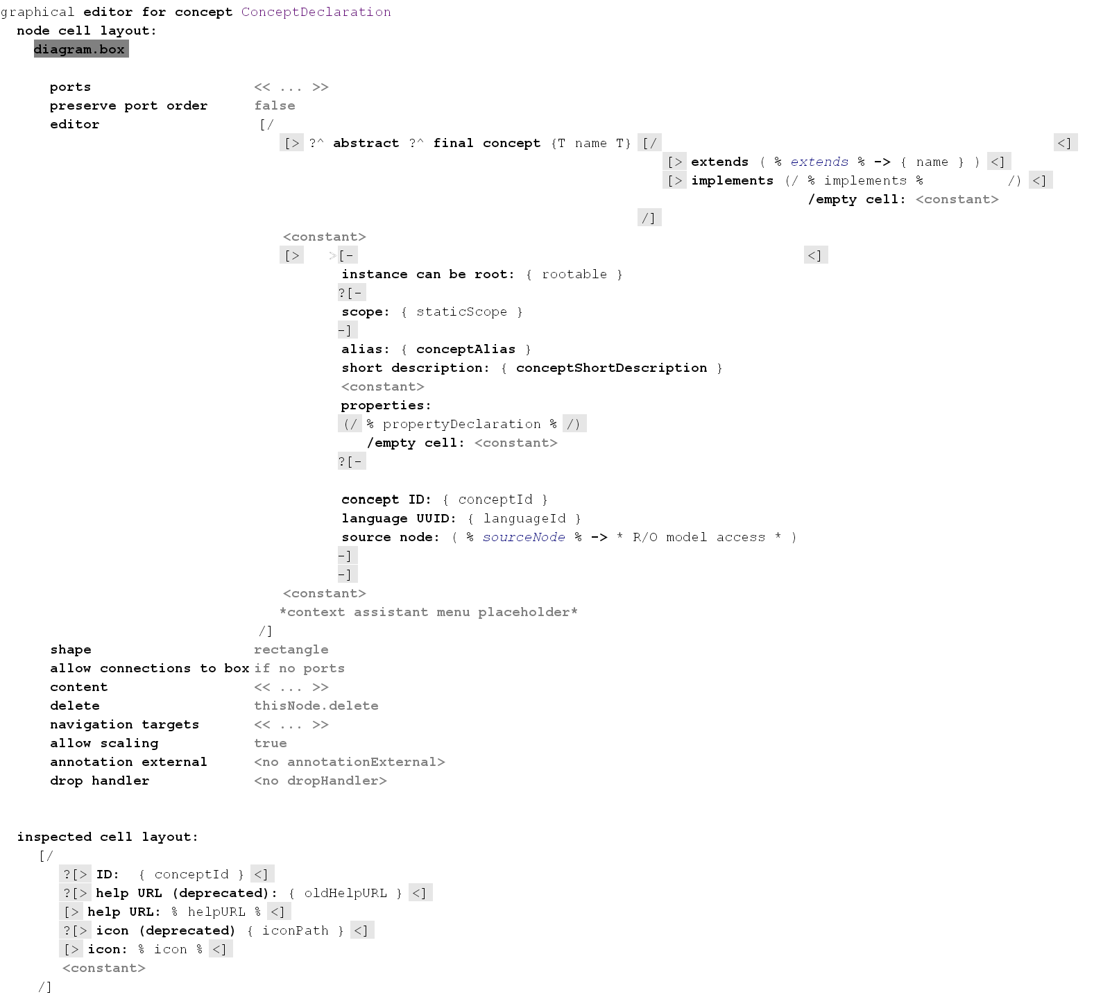
For the editor of the box, we can get inspired by the original ConceptDeclaration editor (e.g. find it by pressing Ctrl/Cmd+N+N, searching for ConceptDeclaration_Editor and pressing Enter): just copy the editor from there and paste it into the editor part of the diagram.box. Then you can remove or add whatever you like. A final version of it could look something like this:
Since we are making new editors anyway, we can also add en editor for a relation (we will only do one, since the other relations are pretty much analogous). Let’s pick AbstractConceptChildRelation: it has a bunch of references (from AbstractConceptDeclaration (which could be ConceptDeclaration or InterfaceConceptDeclaration) inherited from AbstractConceptRelation, to AbstractConceptDeclaration, and linkD which is a LinkDeclaration – a child of AbstractConceptDeclaration, which could represent either a child or a reference in a language’s concept or concept interface). Again, create an editor for AbstractConceptChildRelation and add in a diagram.edge:

The resulting editor will look like this:
![]()
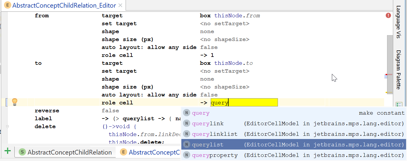
At the from section, we can fill in the target, which is the from of AbstractConceptChildRelation. The diagram editor language has a special keyword for this, called thisNode. So the target of from is a box that points to thisNode.from (so the box at the side of the from reference). We also want to fill in role cell, since that allows us to show multiplicities on both sides of the child relationship. For the from side, this is easy: since a parent always can contain zero or more children, the cardinality at the parent-side is 1. At the to-side, this is more complicated, however: the structure definition has the information about the multiplicity at the child side (it is stored in node.from.linkDeclaration.sourceCardinality).
Now we have a problem: with the normal MPS editor mechanism, you cannot project properties or editors that are not a direct child or reference of the concept’s editor. Sure, you can use a read-only model access, but that access will be read-only. Aha, but you could use a read-write model access, right? Sure, but with it you can only use strings and it is quite less safe than just plugging in an editor construct like a property, reference or child projection. To solve this problem, enter the com.mbeddr.mpsutil.editor.querylist extension from Itemis. Querylist allows you to just project properties, children or references from any node that you can find from the current node by means of an smodel query. In order to start using querylist, press Ctrl/Cmd+L+L, search for com.mbeddr.mpsutil.editor.querylist and then press Enter to import it. Now you can add a querylist at the role cell of the to section (use only querylist; all the other query* elements are deprecated, since you can to everything with the querylist construct):
To query for the concept whose editor you want to access, you have to click on querylist and open the inspector (e.g. Alt+2):
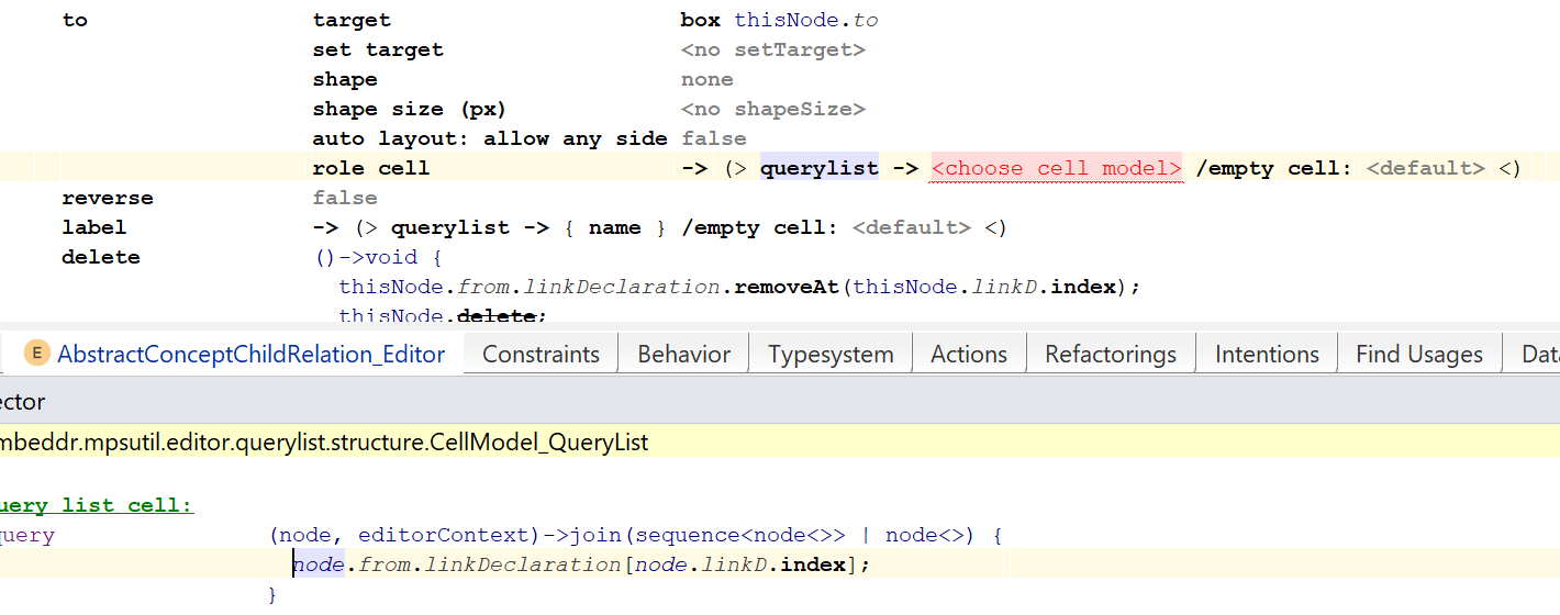
So the smodel query specifies that we want to be able to project properties, children or references from the LinkDeclaration that is connected to the from reference of the current node (which is an AbstractConceptChildRelation). The node.linkD.index is a way to find the linkDeclaration that is coupled to the relevant line in the diagram.
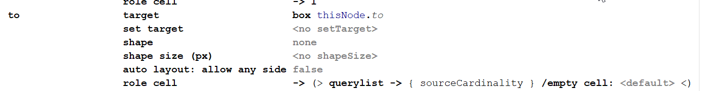
Now we can choose to project sourceCardinality (Ctrl+space in the querylist cell model and choose sourceCardinality from the completion menu). The final version looks like this:
OK, these were the hardest parts of building a graphical structure editor for MPS. Of course there is some more operational code to add to really make it work, so I will give some pointers on how to that. But first, let’s see how an editor for TestLang would look like when it’s finished:
In order to be able to drag & drop concepts and interface concepts onto the diagram canvas, you need to specify palette entries in the ConceptStructureRelations_graphical_Editor. See the code sample on how to do this. Once you have done this, you get entries like this in the diagram palette:
For each of the relations, you need a way to create the relation. The diagram editor has anchors on the boxes in order to drag a relation from box to box, e.g.:

The picture above shows that if you point on the +, you can create 4 types of relationships (C for child as a target, R for reference as a target, E for extend, and I for Implement). You need to add code for that. In the sample, you can find this code under the connection creators section of ConceptStructureRelations_graphical_Editor.
You need to specify what happens if you delete a relationship. For an example of such code, see the delete section of the AbstractConceptChildRelation_Editor.
You need to add editor for the other types of relations that were described in the graphicalstructureeditor language design. Finished versions of these can be found in the code sample.
When you create an instance of a ConceptStructureRelations for the first time in a language of your choosing (see an example in testlanguage), then it will look very disappointing, like this:

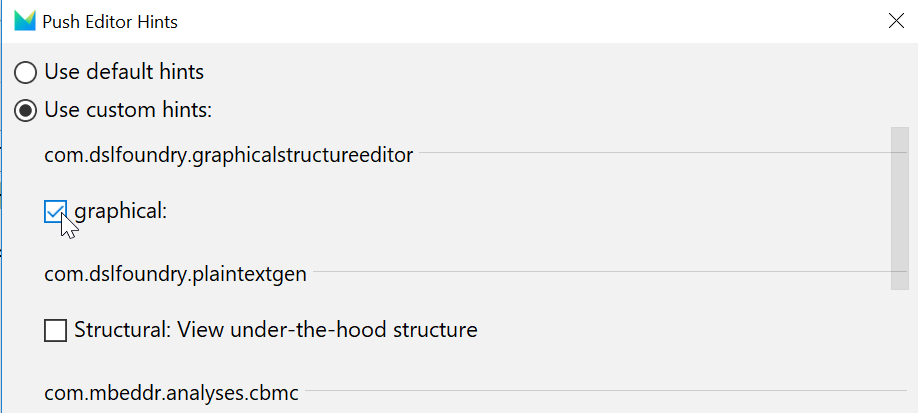
What you need to do in this case, is to push the right editor hint:
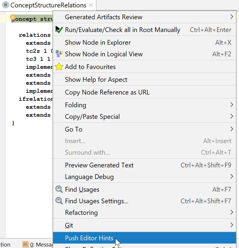
and then:
This will show the diagram editor.
Bonus: you can write an intention on the ConceptStructureRelations concept that reads the structure of a language and synchronizes the diagram with it (useful for adding a diagram to an existing language or to update the diagram when you’ve edited in the “normal” way). An implementation of this can also be found in the code sample.
What’s left to do on an actual graphicalstructureeditor implementation: the graphical structure editor language that is described in this tutorial exists at https://github.com/DSLFoundry/mps-graphicalstructureeditor. Although it already makes it possible to do some basic language structure editing, it also has some limitations. For example, there is currently no way to edit extensions to languages outside the “current” language (i.e. the language in which the ConceptStructureDiagram is situated) graphically, since this involves making design choices on how to represent this in the diagram (such as: how much of the context outside the current language must be shown?). There is curently a list of issues for the graphical structure editor which can be found here: https://github.com/DSLFoundry/mps-graphicalstructureeditor/issues. If you feel like contributing, consider giving more ideas in forms of issues or maybe discuss on the issues how to solve them (or maybe even do a pull request to solve some of the issues).
I hope that you have enjoyed (or were at least helped by) this tutorial. Feel free to leave feedback for improvements or new information!
Is there currently any way, or step by step, or simple example of graphical editing on MPS? Without importing mbeddr? I just tried to import the github project and use it in MPS 2018.1 but I am getting several issues that make the build impossible. Before and after migration several references are broken and I have not enough experience with troubleshooting in MPS.
MPS does have some kind of diagramming editor packaged with it (https://www.jetbrains.com/help/mps/diagramming-editor.html), but I have never gotten it to do what I need.
I would definitely recommend you to go with the graphical editor from MPS Extensions (former mbeddr). The only thing you need to do is to unzip a zipfile from https://github.com/JetBrains/MPS-extensions/releases that has the same version as the MPS version that you are using into your MPS’ plugins directory and then you are good to go. Actually, there is nowadays an even easier way: you can just search for the diagram editor in your MPS through the plugin repository (see http://dslfoundry.com/mps-extensions-available-as-plugins-on-jetbrains-marketplace/).
If you really insist on having mbeddr, here are hints on how to make your own mbeddr-enabled MPS without having to build mbeddr fully: http://dslfoundry.com/how-i-make-an-open-source-mbeddr-developer-release/
Thanks! This is a really useful step-by-step guide for creating a graphical editor.
I would like to mention that it is typically better to capture reference relationships not on the root concept level (where the diagram is shown), but as a normal reference relationship that is a child of the source (or target) of the relationship. As the diagrammatic editor requires an instance to associate data with, it is necessary to make “smart references” to achieve this.
In that case, the ‘from’ (or ‘to’) can then be queried through the ‘ancestor’ of the smart reference. And the relations to be shown can be queried from a nodesQuery at the diagram’s level.
This leads IMHO to a cleaner design of the language, which is much closer to the structure that is also used for textual and tabular editors.